The following is an ongoing article dealing with the use of model railroad modules as a way of furthering ones enjoyment of the hobby and for us here at New England Custom Rail a way of demonstrating some of the many products that we sell over the internet and at shows. (See our Train Show schedule on this website.) Unlike many vendors we actually use most of the products we sell before we enter into any agreement to re-sell a product. We also try to find products that are unique and not carried by many of the local hobby shops. We find that since we use the products ourselves, it gives us an advantage when discussing issues with customers because we have that first hand experience. Here at New England Custom Rail we have made a commitment to sell products which we use and to support the products we sell. We usually can demonstrate the products at the shows we attend, the exception being when table side demos are discouraged.
Three
Modules in Process 12/13/03
November 2002
Here at New England Custom Rail we are always looking to find ways to make model railroading more enjoyable for our customers and ourselves. Like most model railroaders, we do not have a large dedicated permanent model railroad layout. For us and I suspect for most model railroaders, the amount of dedicated space is the biggest issue. Like many people we do set up some temporary track each year under a Christmas tree and run trains through a ceramic winter village, but we have always wanted to do a little more. To those of you who know us, we have specialized in custom painted and decaled pieces that model actual units found here in New England and New York at the tourist railroads. We have also done special pieces for museums, short line railroads, financial institutions and others. As such we are always looking for ways to showcase the products we offer and the services we provide.

Christmas
Village 2003
One of our solutions was to join the National Model Railroad Association (NMRA) and later on one of the local module groups. For us that was the module group within the Hub Division (Hub) of the North East Region (NER) of the NMRA. Now for those of you who do not know what a module is, let me try and give you an overly simplified explanation. A module is a section of a model train layout built to a set of standards defined by NMRA so that additional modules can be joined together to create a portable, changeable layout. The two most popular module standards are for “HO” and “N” scale. The more modules that club members have the larger the layout they can build. For the Amherst Show this year (Feb. 2004) in Springfield, MA the Hub Module Group had six corners, one diamond, one end loop, 46 straight 4 foot modules one of which is a bridge and one six footer in their display. This was the Hub module group’s largest display of the year.
If you think you are interested in building a module find or visit with your local club either on the World Wide Web or at one of the many local train shows that they may be exhibiting at in your area. Talk with the folks and if you are still interested then volunteer to help that group at a couple of shows. Then if you are still interested after say a few months and a couple of shows then it’s time to talk with someone about becoming a member. That’s what we did. We volunteered to help the Hub Module Group setup and take down at shows over a few months (December to April) before finally becoming official club members and buying our module kits.
The first question one is faced with when contemplating building a module or modules is what do you want to model. The second question is how do you fit your ideas onto a two foot wide and four foot long section or sections? Additional questions might be what era and time of year do you want to model. Since we have principally focused on New England we chose to model Crawford Notch, New Hampshire, which contains a small three track yard that exists at Crawford’s Station in the White Mountains. It is an area that goes back to the earliest days (Portland & Ogdensburg Railroad chartered 1864 – Tracks through Crawford Notch to Fabyan’s 1875) of railroading in northern New England and is still in use today by a tourist railroad, the Conway Scenic Railroad. We chose to model a fall foliage scene around 1999 before the latest changes in the Notch. The initial thought was that there was a nice small three track rail yard and there weren’t a lot of buildings, just one rather ornate station and a shack at the other end of the yard, so the modules should be quick and easy to build. Well at least that was the initial thought. The reality is that we already have over nine months into the project and can easily see this taking over a year. Of course we built three modules at the same time not just one. As this project progresses we have found that good scenery (accurate buildings, lots of trees, water, signs, roads and the details that go with them) can be just as challenging if not more challenging as lots of buildings in a city scene. This is especially true when dealing with geographic features that railfans will recognize. Because we were modeling a very popular rail fan location, our goal was to generate the “look and feel” of the area and not a scale replica of the area. This makes things a little more difficult in some cases and easier in others. However, the satisfaction comes from having the general public get excited when they readily recognize the location and ask question about how different features of the modules were built.
April 2003
We initially decided that two modules should be long enough for the Notch area, so we initially bought two “full top” module kits. However, every time we tried to put a scale plan to paper we found that we needed at least a third module if we wanted to include each of the major landmarks in the notch. We needed one module for the Crawfords station area, another module for Saco Lake, and a third module for the notch or “gateway” itself. That meant we needed an area 2’ wide and 12’ long to build and put scenery on. Now we are into a third kit. It took a while but we eventually were able to locate and purchase a third “full top” kit from the club. Something I didn’t mention earlier is that our club offers pre-cut module kits in two forms. The “full top” kit has a section of plywood over the basic frame structure, which makes the module stronger and ridged but also heavier. The second type of kit is the “open top” kit which builds a lighter unit.
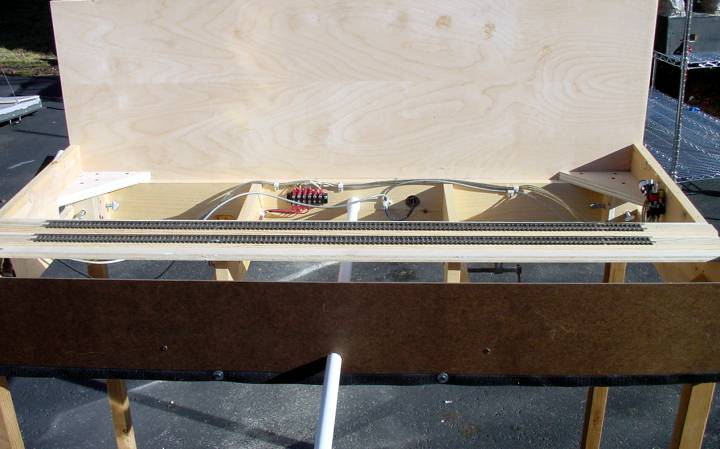
Assembled
“Open Top” Module
The other issue we had to resolve in the planning stages was how would we compromise on the track layout? The national standard requires two mainlines at 5 and 7 inches to enter and leave each module or grouping of modules. The real Crawford Notch only has one mainline through the notch and only one mainline past the station. So for us that meant our first compromise would be changing the track to meet the national and club standards by having two mainlines in each of these places. The next compromise would be where we installed the switches. We chose to set things up such that we created the possibility of passing on either or both of the mainline tracks, at the same time. This would allow us to park a train on any of the three tracks at the station and still have both mainlines functioning by switching around any parked train. Once these decisions were made we could build our modules and layout the roadbed, track and switches. We also could complete our track wiring and ballasting.
Sometimes individual clubs agree to extensions to the national standards to allow themselves capabilities beyond what the National standard initially anticipated. For example the Hub Module Group has standardized on the Lenz DCC system so each Hub member’s module supports the XpressNet wiring system with 5 pin din connections and pass through cable for each module at a minimum. Then either an optional din connection at the rear center of the module or an XpressNet panel(s) on the rear and/or the front. In our case we decided that we would install and XpressNet panels on the rear of each of our modules and an additional panel on the front of the middle (Saco Lake) module. Now we could also complete our DCC wiring as well. Each club has its own guidelines on the building process. Some require inspections at certain points within the building process to prevent newcomers from getting to far along with mistakes that will cause them problems later on down the road. These checkpoints can be very helpful since it gives the new person someone to ask questions of and get a pointer or two from. Another thing to remember, each member of the club is a potential resource of information and experience so take advantage of your opportunities to get some help when you need it. Some clubs even run special meetings once a month where different modeling skills are demonstrated to the members and public at large in an effort to provide an education within the hobby.

Assembled
“Full Top” Module
We had an initial inspection after building the basic wooden module to verify that it was square. Our second inspection dealt with the track work, it verified proper placement of track. The third inspection dealt with the electrical wiring. In our case we had also done the ballast work (which we shouldn’t have). We actually hooked up a Lenz DCC system and ran an engine up and down all three modules and all three tracks, and all six switches demonstrating that we had proper isolation and that the switches didn’t cause problems. Once we had passed these inspections we should have taken our modules to a show without any scenery to verify proper operation within the group before adding the scenery, but by now it was June and the only show during the summer would be the National Train Show in Toronto (July 2003). The Hub Module Group had decided that the modules going to the show would be finished only (clubs preference) or those with initial scenery and no bare wood showing.

Modules
ready for Testing
That left us with a problem, how to get far enough along that the club would accept our modules for the show. Traditional modeling techniques with plaster and wire screening would require too much time; also the end results would weigh too much and wouldn’t travel well. We were looking to build some mountains, a notch, a lake, the start of a river, a road, a couple of parking lots and a raised area. We had about six weeks of part time effort to accomplish this. So we were searching for something that would be light weight and quick and easy to build.
We had been told about a new modeling technique which utilized a binary or two part foam system “Bragdon Geo Foam” which yielded a very strong and very light weight form of scenery. After a little investigation we decided to give it a try. The goal was to have something strong and light that was easy to work with and would not develop cracks when traveling in a trailer and being bounced around. The Bragdon foam process turned out to be just what the doctor ordered. We were able to use commercial insulating foam which we cut and formed with a simple hot wire cutter as a base for a mountain ridge that ran the length of all three modules. We also used it to create a small raised area on the station module. We then were able to cut out the lake area as well as the outflow stream which becomes the head waters of the Saco River that flows out of New Hampshire and through Maine on its way to the Atlantic Ocean. We next started covering the ridge, the lake bottom, the stream bed and the raised area with sections of the Bragdon foam panels. We used the newer method which layers the foam with two layers of inexpensive fiberglass screen material.
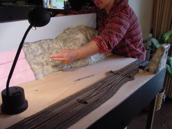
Foam
panels being applied
This foam screen sandwich goes down quickly and with none of the dust and mess associated with a more traditional hydrocal/plaster scenery process. As you can see in the photo above you just lay the stuff down and trim with a scissors or a knife. Another nice feature of the foam process is that the material can be reshaped later if necessary by applying heat. You may also see in the photo some pencil line on the plywood tops. One of the things we did was to roughly draw in the details of features we were going to add to each module so we could get a rough idea of how things related to each other. We continued covering the modules with the sections of foam panels. Our next major task was the creation of rock out crops and applying them to the finished ridge line.

Applying
Vaseline to a rock mold
Creating the rock outcrops was done with the same Bragdon products. In the picture above a thin coat of Vaseline is being applied as a mold release agent to a typical rock mold. Then we applied a thin coat of spray white lacquer paint that was let dry. Next you pour a small amount of the cast satin material which picks up the fine details and gives you a hard outer shell. After which the original foam is used as the filler for the deeper voids. Once a rock mold sets up (around fifteen minutes) it is removed or pealed from the mold and applied to our ridgeline. We chose to lay down some stripes of hot glue in the area where the out cropping is being applied to hold it in place.
After getting the ridge and the two rock outcrops covered, the next major project was to build the road through the notch (NH route 302). In our case, the road starts by going between the back ridge and the middle rock outcrop. It then swings slightly towards the train tracks and then swings back toward the ridge as it passes the large parking lot near the tracks. The road then curves onto the second module working its way past another smaller parking lot and then around the lake. Then as it enters the third module next to the station area it angles towards the back again and continues up a slight incline and off the back edge of the module behind some trees. As you can see this is not a simple straight road. (So much for my simple scenery theory.)
For the roadwork I used the Woodland Scenic road system products which are a form of a plaster which worked but was no fun to work with. The problem was you had to make sure you got all the little lumps and clumps out of the material (almost like mixing a cake batter), applied it to the area and got it smooth before it started to setup and get stiff. Although not the easiest stuff to work with it does yield a pretty nice result. You must let it dry before finishing it with any surface coloring. I finished my road with the blacktop paint also from Woodland Scenic. The next process should have been to apply the road striping but at the time I didn’t even think of it. Because our goal of being ready for July, I would have skipped that step at this time anyways. We did go back and add the stripes but not until September.
With the road in place the next major task was to cut out the lake, the river and the drainage areas, as well as the culverts which take the river out of the Notch under the highway. Cutting these irregular shapes was done using a rotary saw. This made getting the many curves around the lake relatively easy. Once these cuts were complete, the binary foam material could be installed creating the bottom of the lake and streams.
Road in
place and drying
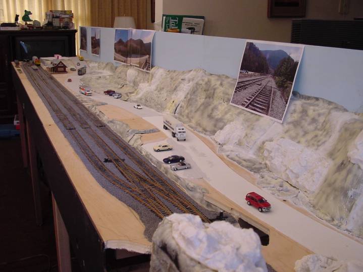
In the picture above you can see that the foam has been installed almost everywhere except under the rail bridge from the marsh to the culvert which exits the notch under the highway for the Saco river. Something else you may notice is the photos taped to the backboards. This was another one of our techniques to help us visualize the area we were modeling. You can also see that we have added a number of rock out crops also made with the Bragdon foam system. You will also note that seams have been filled with simple DAP compound like you would use to seal a tub or window. The next issue for us was to prime everything with an artist acrylic white gesso before applying any artist acrylic colors. Once primed then we painted everything except the rocks with a latex earth tone paint. For the rock coloring we applied several washes of color in an effort to try and match what we found in the photographs we had of the rock formations in that area.
We had decided that we would not attempt to cast any water into the lake or the rivers at this time. That was a task we just wanted to wait on to give us a chance to do a little more research on. Another task that was being put off till later was the “Crawford’s Station” model. We have the kit but had not built it yet and we gave ourselves a goal of having it in place for another major show in February (Amherst Railway Society at the Big E in Springfield MA) of the following year - 2004.
Grasses were the next major addition after which we could start applying trees if time permitted. By now we were running out of time. We had chosen to make most of our trees. We used the Woodland Scenic armatures and shredded foams, both for the deciduous and for most of the pines. This was an effort to keep the cost down and when you need over a thousand trees it’s the only way to go. Considering how many trees we had made and the time we had left we could not deal with all three modules; however we decided to apply the few trees that we had to only one module, the Notch module. We did not have enough trees to cover the module the way we wanted to but it would be a start. Our rational was that we wanted to paint in some ridges on the backboards of the other two modules. So in early July 2004 the work on our three modules was stopped so they could be packed into a trailer with nine other modules for the trip to Canada, see the pictures below. Although a long way from being done they were far enough along to meet the clubs definition of “scenery” or “no bare wood”.
![]()
Crawford
Notch
![]()
Saco
Lake
![]()
Crawford
Station module with the wrong station
July 2003
The club actually took a third place in the competition for best club display at the Toronto “Maple Leaf 2003” convention and train show. This is the second time the Hub Module Group had placed in an international competition. In the individual module competition one of our club members took First Place and another member got an Honorable Mention for their modules.
Once back home we had a ton of work to do to get things further along before out next commitment, which was in November at the Hub Division train show November 2003. The first thing we did was get the work started on painting some ridges along the backboards of two of the modules. Another feature that we wanted to add was some white fluffy fair weather clouds in the sky. A flat blue sky is just not very realistic for my taste. For this I enlisted my daughters help since she has a minor in art. Again I roughed in a pencil sketch of what I wanted the ridges to look like, and then turned the process over to her for completion. This took a considerable length of time (approximately 30 hours) since there were thousands of trees both evergreen and deciduous in fall colors to be painted in. Below you can see the beginning of that process. Our goal was to create a carryover effect between the modeled trees we were planting in the foreground and the background that was painted onto the backboards. What we found was that it gave us an effect of a greater depth of field as the foreground trees blended into the background painting. This blending of the foreground trees and background painting was just what we were hoping for.
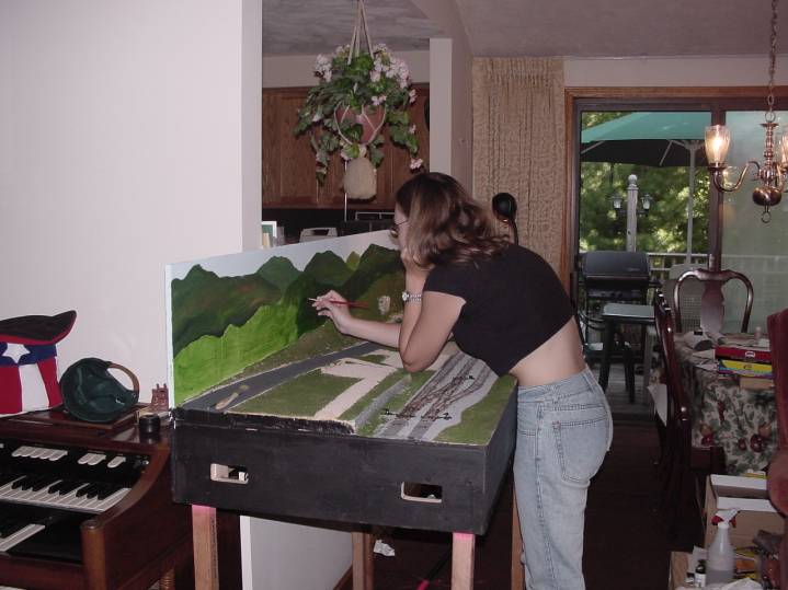
Background
being added to the backboards
One of the questions that we are constantly being asked is “How do you join rock outcroppings?” The answer is simple you place them so they overlap a little and just press them into place. At the show in Toronto one of our club members, whose module was next to the Notch unit, asked us why we didn’t cover the vertical end of our ridge with a large rock mold. We answered that we didn’t want to get too close to the next module with rocks. He basically said that we should add it so as to give it a more finished look. (He should know he got the Honorable Mention in the individual module competition.) So we got a large rock mold from Bragdon and cast it and cut it to fit and added it three months (October 2003) later. When at the November show people could not see where the older rocks ended and the new rock began. Pretty much your rocks will have a series of layering lines or strata. You should try and find another mold with similar lines. That way you can line things up so one continues into the other and gives you the continuation effect that you are looking for. Then it’s only a matter of matching or blending the coloring to make the addition look like it has been there all along.
Probably the one scenery feature that gave me the most concern was adding water (in our case clear casting resin) to the modules. After reading all the books dealing with the subject, we were still uncertain how we wanted to proceed. We talked with Joel Bragdon, the creator of the binary foam system we were using, and were told that one of the oldest methods (and smelliest) was the use of Clear Casting resin. It would yield the best long term results. The caveat was we had to have a place to do it with plenty of ventilation. The newer materials, which deal with the smell issue, have other problems and may crack or yellow with age. So we decided to place the modules in the garage for this process. The other issue I knew about was creating some kind of barrier to keep the liquid resin from running down the face of our modules where the water edge was going to be. Other club members warned us of this problem because they had problems with it in the past. What I did was to cut a flat piece of plastic from a one gallon milk jug. I then slid it behind the fascia board to use as a barrier during the pouring and curing process. As you can see in the photo below I was able to get a nice vertical edge at the front and sides of my modules.

One of the things we found was with this clear resin approach you needed to model your stream bed since it is visible. In the photo above you can see some of the rocks and vegetation that we added as details before pouring our water. The biggest problem I had with the water was in the lake itself. Because of its large surface area, the casting resin has a shrinkage factor of around (7%) which became an issue. The lake edge pulled away from the shore. My fix for that was to go back around the edge with more bank material (fine sand) and then seal it with a clear artist mat medium. Between the lake, the marsh drain and the river we ended up using five quarts of the clear resin for our water effects across two modules. (We found that buying the materials at a crafts store saved us around 50% compared with a hobby shop.)
One of the other tasks we took on was to add road stripes to the highway. Route 302 has a double yellow line all the way through the Notch. It also has solid white stripes on both sides of the road as well marking its side shoulder areas. I decided to airbrushed in the stripe with a lot of masking. This is a process that would have been simpler if it had been done before the scenery had been started. Simply stated I didn’t plan it until after seeing other clubs modules and roads at the show in Toronto. There I looked at some of the roads on other clubs displays and saw how much it added to the overall effect and decided that I needed to add it to our modules. It does make the highway look a whole lot nicer.
The other major addition for the November show was the planting of several hundred trees. With the background painted we could now complete the planting of our foreground forest. Pretty much we went back to our reference photos to determine what type of trees went where. We also positioned trees by type and color to blend with the background as best we could. We are very familiar with the Notch in fall because of our past hiking in that area. Additional features that we wanted to have were the different trail heads which are in the area. This meant we needed to leave a path around the lake for example. It also meant that we had to develop a technique for producing the trail signs in HO scale, along with other signage that is located throughout the notch. We also had to build at least the two visible bridges for the lake area. Remember our goal is “Look and Feel” not total geographic accuracy.
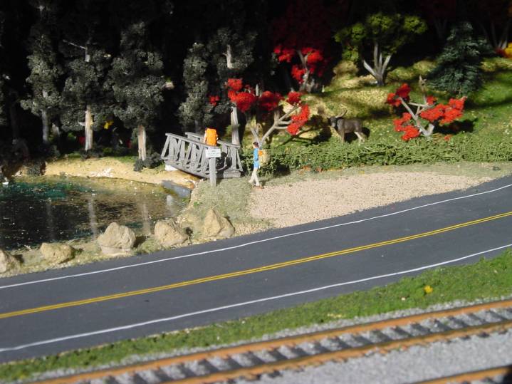
Bridge
over Saco Lake dam with AMC trail sign, hikers and moose hiding in the
shadows
One of the last details to be added was a grime stripe between the rails and through the switches to give the rail yard that heavily used look. Actually the first and second tracks are the only ones being used by the tourist railroad at this time. In reality, the third track is currently overgrown with weeds, blocked and pretty much unusable, but that is reality and so we chose to ignore that and make our yard completely functional as it was in years past.
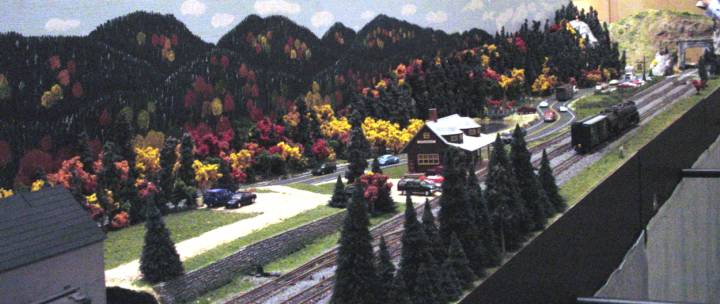
Below is a picture of the three modules again (December 2003) as they have evolved. They are not finished yet but are much further along than they were during the summer trip to Toronto. One thing that can probably be said for most module owners, no matter how hard they work on their units there is always something else that they may want to do to make it even more interesting for the next show. So for us the work goes on as we continue to shoot for the goals we have set for ourselves for February 7th & 8th 2004 and the Amherst Railway Society show at the Big E. We will have these modules with the Hub Module Group exhibit and we will also be there as the vendor “New England Custom Rail” so please stop by and say hello and we hope to see you there.
![]()
Modules
at Museum of National Heritage December 2003
January 2004
Work continues on meeting our goals for the Amherst train show. Our commitment is to build the correct train station and get it on the module. The Crow River kit is a beautiful craft kit. However, it was not intended for use on a module, the roof sections are cast out of hydrocal/plaster. This makes them more fragile than is needed for the rough use they would see traveling around bolted to a module being set up and then taken down on a regular basis. Below is a picture with the beginnings of the station positioned to see how things will fit? The plaster roof parts are white in the photo and have not been primed. As you can see the station is quite different from the one I had been using as a place holder in the past at the earlier shows.
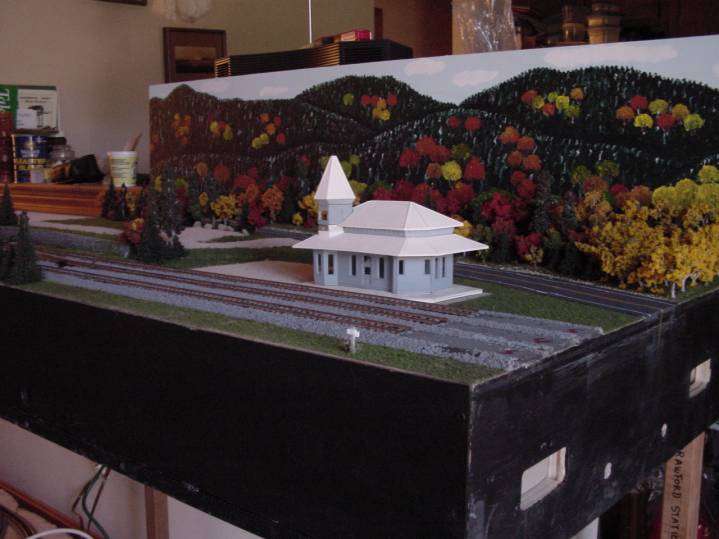
Crawford
Station in process
My solution to the fragile plaster parts was to make my own molds and recast all of the roof sections and the floor in a plastic (Cast Satin resin). Here we are again trying out another new product from Bragdon Enterprises, their Silicon RTV (Room Temperature Vulcanization) products. They offer two grades of Silicon RTV, the white is designed for creating molds that will be used between 100 and 200 times, the blue is designed for creating molds that are to be used 50 or so times. We first tried a pound of the white Silicon RTV to create a mold for the turret roof section since it was the smallest piece and the only one for which we had enough material to try. First I built a mold box out of a sheet of plastic as the base and then I cut and duct taped the box walls out of corrugated cardboard. The biggest trick in working with the silicon is getting the measurements correct when adding in and mixing the catalyst. In our case I used an electronic postage scale to get accurate gram weight measurements. (This is the same scale I use to determine correct car weights when bring them up to the NMRA recommended weights.) I used the plaster part as my master and covered it with the silicon mix. After working the bubbles out of the initial thin pour, the mold set for a couple of hours before the second pour was made to complete the mold. This had to set and cure for about 24 hours. The next day the walls of the mold box were peeled back, then the base was separated from the mold, then lastly the mold was separated from the original part. The end result was a very nice mold that would produce a very clean replacement part out of resin. Two things I learned from this first try at making a mold. First: I didn’t need to glue down the original part as thoroughly as I did, a simple around the perimeter bead of glue would have done just fine. This glue serves two purposes, one to hold the part in place, and two to prevent silicon from getting under the part. Second: I didn’t need to use as much duct tape as I did on the inside of the mold box. It only made it more difficult to take apart. For subsequent mold boxes I did not use any duct tape on the inside of the box and it worked fine.
The next step was to try out the mold by casting the replacement roof turret. Once the Cast Satin had been mixed it was then slowly poured into the mold in an effort to eliminate any bubbles from being trapped in the new roof section. After about twenty minutes the new part was successfully removed from the mold. The result is a light weight strong replacement for the plaster turret roof section. Now all we needed was some additional silicon RTV (5 more pounds) and we could cast the additional parts. For this kit it took me six pound total to make the molds for all four parts. Since I do not intend to make lots of roof replacements I chose to make the rest of the molds from the economy grade silicon RTV (blue RTV good for around 50 casts). Once all the molds where completed it was then time to cast my replacement parts. You can determine how much cast satin you will need by filling a mold with water and measuring how much it took. Then thoroughly dry the mold before casting in it. I did this for each part and used a white lacquer as my mold release agent. The end result was very rugged parts that would travel without any problems.
My next problem was to correctly match the existing station colors. The station has had at least three different paint schemes in the past. The current scheme of a yellow, green and reddish brown was first applied some time in the sixties or late fifties. Prior to that there were simpler paint schemes in grays and greens. This is an area where the kit folks could have been a little more helpful, but they left things pretty much up to the individual. Since we are modeling 1999 – 2000 era we had to reproduce the current complicated paint scheme. I found that the yellow on the station could best be approximated by mixing Floquil’s UP Armor Yellow with Antique White in a 50/50 mix. I then used Floquil’s Dark Green and Tuscan to complete the colors for the station. These seem to match the photos I had taken the best.
The kit is a craft kit so the fit of the pieces is not as precise as most things are today so you have to test fit the parts first, then make any adjustments, then test fit again before gluing each part in place. This is what makes building this type of kit so time consuming. I was able to do most of the painting with an airbrush. However, all of the windows boxes and wall trim had to be hand painted – a very time consuming process. The end result does generate the look and feel of the real station and my color scheme does go well with the rest of the colors on the station module. See the photo below.

Crawford
Station model in place for Springfield 2004
Mounting the station to the module was done by gluing the floor to the module top and then drilling through the floor in two places - one hole in the back corner next to the double door entrance and the other in the front area behind the solid wall in the ticket agents’ area. We ran a threaded rod up from underneath the module and used epoxy to attach the rods to the roof segments. With this arrangement the roof becomes removable for viewing or working on the interior. This will allow us easy access to install the lights and fireplace at a later date.
Another detail that was added was the four signal masts that are part of the manual switch machines we had installed. Since our track layout is different to support the two main line (module requirement), my masts will be a green ball symbol for straight on the main and a red arrow for caution when the switch is thrown pointing in the direction of the change.
There are a number of additional feature that I plan to add to this model. Like a complete interior with additional walls, lights and a working fireplace and some digital sound effects. But these additional features will have to wait till after the Springfield show.
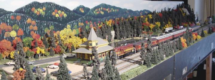
Modules
with CSRR Valley Train as they went to Springfield February 2004
The Springfield Show was a big success. Our vendor location was within sight of our modules as they were part of the Hub Division display. There were over 18,000 visitors this year. So now we can relax and take some time to work on the final details that we are planning on to finish our modules. The AMC bunk buildings that used to be on this site are one item we would like to add. Another item we will experiment with is stationary sound units. We were thinking of some water sounds for the notch module, some station sounds for the station module and possibly a thunder storm for the lake module. The other things we need to add more of are the road signs on 302.
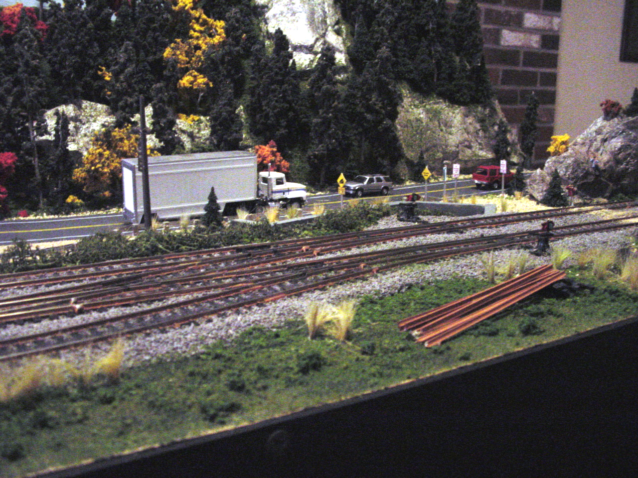
Well it is August 2004 and we are experimenting with additional scenery details on the Notch module. This is the module we have used as our test module. That is to say every new technique is tested here to see how it works. One of the areas that needed attention was the wide flat green grass areas, which look artificial at best. What we have done to break up the flat green spaces is to add some small clumps of taller grasses. Since we are dealing with early fall we mix three different shades of grass - yellow, orange and light green to give it that change of seasons effect. These grasses are planted by drilling a small hole the filling it with white glue then stuffing the grasses in the hole and last we trim and spread the clump to give it a wild look. Most of our clumps of grass were located next to the water going under the tracks, along the side of the road and along the tracks. The other technique for breaking up the flat green spaces is to also add some small green scrub which is attached with diluted white glue.
Another detail which I have added to this module is a pile of railroad ties and a pile of rusted rail. These items stack off to the side to give us the idea of some track maintenance being done over time in this area and supplies being left over from the last cycle.
If you are modeling a road then road signs that are accurate for that area are virtually impossible to find. So what I have done is make my own. In my case I made decals and applied them to painted plastic sheet stock and then cut them out with a pair of scissors. (You could also print them on a white adhesive label with an ink jet printer.) I then mounted them on short sign post again made from plastic scraps. Next I drilled a small hole; I then placed a small amount of Wathers Goo on the post bottom and set the signs in place. The end result can be seen in the picture below.
Added scenery details August 2004
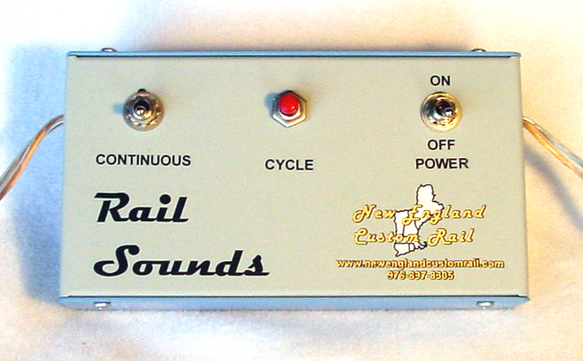
The last update to this module is the addition of the stationary sound module of fast running water flowing down our rocky headwaters of the Saco River. Using a small sheet metal box, I installed a sound card, a pair of toggle switches and a push button for controls (see picture below). For a speaker, I used a small one inch round unit mounted inside a 35mm plastic film can. This was then attached to the module so that the opening for the speaker was hidden under the rail bridge, which also acts as an additional baffle. The power for the sound card is supplied by the auxiliary AC supplied by the module (white circuit). With everything connected, the control box was mounted on the inside of the backboard. The end result is the unit and its wiring are up and out of the way and the controls are easy to reach. A person standing behind can activate it by reach under the back corner and simply flipping a switch or two depending on what they want to do.
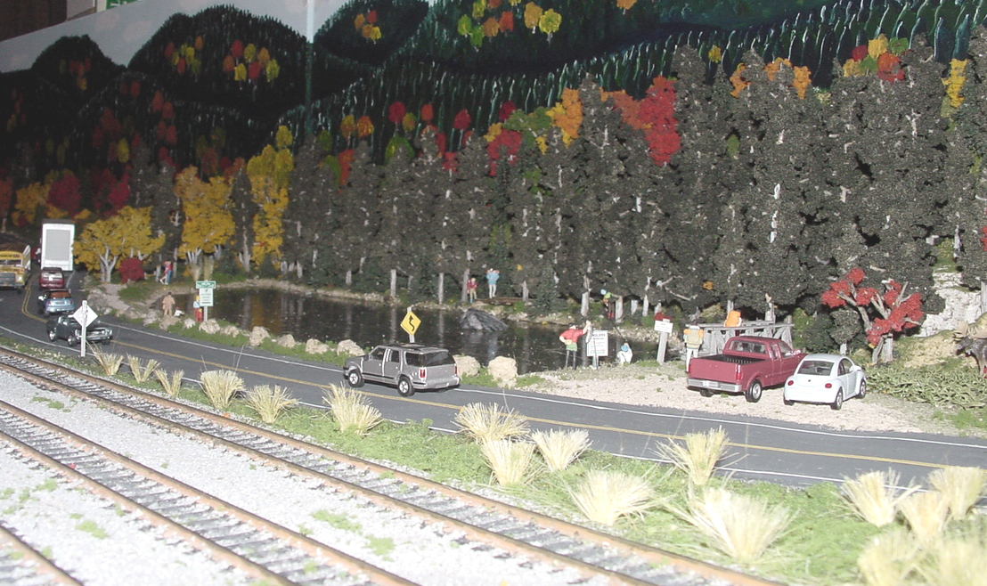
During November 2004 I pulled in the other two modules, Saco Lake and Crawford’s Station. Both of these will get additional detailing similar to what was done on the Notch module before being shown again at Springfield 2005. On the Saco Lake module, four location specific road signs were added along with two generic road signs. One of the added signs was the posting for the Anglers, announcing the fishing season and regulations for Saco Lake. Another was for the Cog railroad 4 miles down the road. Yet another announced that Saco Lake is a historic location in the Sate of New Hampshire. These kinds of details can only be added if custom made. However, they do add considerably to the uniqueness of these three modules. Once those signs were in place, it was time to add a pair of Fisherman to our fall scene by the lake. I also have added tan gravel to the path along the front of the lake. Before I only had a colored stripe between the low grasses. I have also added a tourist family on this front path heading back toward the station to help finish off this module. This module will also be getting a stationary sound module. The one I have chosen is that of a brief mountain thunder storm, one of those late afternoon events that rumble though the mountains on a fairly regular basis. The goal for this unit is that it be activated via the push button rather than running constantly. The question is how to mount the speaker? The speaker I have chosen was one that gave me the best low bass sound component of the thunder.

Speaker Mounting
What I came up with for mounting the speaker was to take a small round ZipLock storage tub and cut the upper lip off of the tub. Then I cut two short recesses into the remaining piece 180 degrees across from each other. These slots will receive the bottom side of the upper surface support and assure positioning. Then I cut a third recess into the tub for the speaker wires. Next I took a small square of double sided mounting tape and applied it to the back of the speaker magnet and to the inside bottom of the tub. Lastly I applied another strip of heavy duty double sided mounting tape across the outside bottom of the tub centerline and then slid everything into the gap of the top support. The two notched out areas hold it centered and the mounting tape holds it in place. The end result is a speaker with a soft flexible shield which bounces the sound off of the bottom of the module top yielding a pretty good sound effect without having to modify the existing module scene or fascia with any kind of a hole. Next I dabbed some small amounts of white glue to which I applied some green grassy spots between the rail lines to give it more of a country look. The last thing to be added was some additional grasses and small clumps of scrub brush to break up the flat gassy areas giving them a wilder look.
Detailed Saco Lake Module
The last module to get this additional second round of attention is the Crawford’s station module. The station itself I would like to add an interior to with lighting and a fireplace. However, the first addition is to add the three station signs to the station. Again these were scratch built. They were mounted to the roof supports which are attached to the station walls. This way we can maintain the removable roof capability. There will be one unique sign added at the former driveway to the AMC hostel that was there prior to the building of the Wilderness Center which opened in 2004, that now sits on the former location of the historic Crawford House hotel. This module will also be getting a sound unit; it will be of a steam engine idling at the station with people sound in the background. This was chosen to complement our model of the Conway Scenic number 7470 steamer which has been a major attraction pulling a train to this station in the past on Rail fans weekend. The speaker mounting will be done the same way it was handled on the Saco Lake module. That way there is no need to modify the existing scene, which makes things much easier.
This module has the only building and sign which will get any lighting. The lighting will be the last major addition for these modules. The sign has two lamps one on each side which improve the night visibility of the turn for the AMC Hostel that was there until 2002. The lights I am using are modeled after the old time fixtures which consisted of a porcelain metal shade that was green on the outside and white on the inside. This is not an exact replica of the last sign there but will definitely generate the look and feel that I am looking for.
I will also use these fixtures to light the inside of the station. For the station my initial plan is to mount four lamps. One thing to remember is that the restored station has been a retail outlet and tourist information center for the AMC and only recently did the Conway Scenic restore tourist train traffic to the area during the summer and fall months. This being the case, my plan is to place two lamps over the central retail space. A third lamp will light the retail space that used to be the women’s waiting area. The fourth lamp will light the cashiers/information desk which is in the area of the original ticket/telegraph office. Lastly there is the possibility that I will try and add a fire effect to the fireplace. My other option is to leave the fireplace empty which may be the way we leave it for a while.
The trick for these modifications is to get a transformer that will take the 18 volt AC current of the modules white circuit and transform it into a clean 1.5 volt DC current needed for the micro bulb light fixtures. For this I am going back to GRS Micro Lighting for one of their transformers. I will be using the GRS125 regulator which takes an input of between 4 and 20 volts AC and converts it to 1.5 volts DC with enough output to support up to 50, 15 ma bulbs. Because this will be an install on a module I will again mount this circuit in a vented metal box to protect it from being touched. I have the additional requirement that I find a transformer that will provide an acceptable AC voltage and amperage when the modules are not being displayed as part of the clubs display. For this I have ordered a GRS CK1009D. This unit will supply me with enough AC power for the lights and the previously installed sound cards for all three modules with no special wiring changes and enough power for additional modules in the future.
With the electrical upgrades being added the question is will they be there for Springfield. Also will the station interior parts keep this unfinished until we go to National Show this summer in Cincinnati (July 2005)? Parts availability is always a problem within this hobby. In either case the modules will be pretty much finished this year. The bottom line is that if you join a module group then the building of a module should be considered a long term project that will keep you busy for months if not a couple of years. The advantage is that you will have the ability to participate in exhibit events while your project is in process. When you finally get to the point where you think it is done then it must be time to start building another unit. Basically it’s a never ending hobby. You can get out of it much more than you put into it when you work with other members of your club and when you experience the publics’ interest and enjoyment in your module(s).